Home
/ Alternator Circuit Explained : Me08 : Disconnect the wiring from the existing alternator.
Alternator Circuit Explained : Me08 : Disconnect the wiring from the existing alternator.
Alternator Circuit Explained : Me08 : Disconnect the wiring from the existing alternator.. P0562 (charging system low voltage). Wiring diagram how an alternator works. The working principle of an alternator is very simple. Any short or open circuit or wrong connection can cause a sudden surge of voltage that will damage electronic parts. Wiring diagram how an alternator works.
The excitation system on a ac alternator refers to the way the alternators voltage is initially built when rotated and controlled while in use. Never make or break any connection while the engine is running. The first is the alternator output rating, which is the amount of current that a unit is capable of producing at a specific rotational speed. In the compressed air system cubic feet of air is the similar measure of quantity. The alternator has a rotor that spins when the engine cranks.
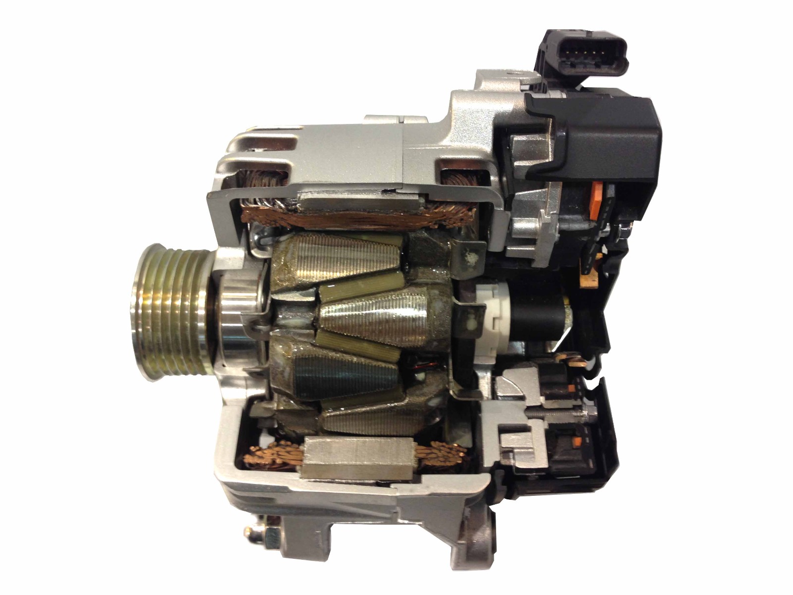
How Alternators Work from www.autoelectro.co.uk They can produce more current. Opening the alternator reveals a large cylinder with triangular finger poles around the circumference. The headlights, dashboard lights, radio and interior lights all rely on the alternator to keep the battery charged and the car operating. There is another circuit in the alternator to control the charging system warning lamp that is on the dash. Alternators that have one positive wire connected to the alternator has the ground connected to its case. The voltage regulator senses the alternator output voltage, though the monitoring location varies. As the rotor turns within the stator windings, the magnetic field of the rotor sweeps through the stator windings, producing an electrical current in the windings. A basic alternator is made up of a series of alternating finger pole pieces placed around coil wires called field windings that wrap around an iron core on the rotor shaft.
Once the vehicle is running, pulleys on the running engine rotate a belt connected to the alternator, which then causes the internal coils of the device to generate power to replenish the battery for the next start and provide ongoing electricity to operate the vehicle's accessories and lights while in operation.
Part of that circuit is another set of diodes mounted inside the alternator called the diode trio. The first is the alternator output rating, which is the amount of current that a unit is capable of producing at a specific rotational speed. The voltage regulator senses the alternator output voltage, though the monitoring location varies. The alternator has a rotor that spins when the engine cranks. For instance, a 100a alternator has a rated output of 100a, which means that it is capable of providing 100a when the. The basic operation is as described below, except the alternator only uses 6 diodes and has an external regulator and energisation circuit. An alternator works with the battery to supply electricity to components of a vehicle. 38+ fakten über alternator circuit explained: 12 volt alternator installation operation manual introduction thank you for choosing a balmarr high output alternator. S is used by the regulator to monitor charging voltage at the battery. Opening the alternator reveals a large cylinder with triangular finger poles around the circumference. A voltage regulator converts the power generated by the alternator to direct current. The headlights, dashboard lights, radio and interior lights all rely on the alternator to keep the battery charged and the car operating.
Once the engine is in the idling mode the dynamo starts getting a field current through the ignition warning lamp. Wiring diagram how an alternator works. A basic alternator is made up of a series of alternating finger pole pieces placed around coil wires called field windings that wrap around an iron core on the rotor shaft. The voltage regulator senses the alternator output voltage, though the monitoring location varies. The term alternator output refers to two distinct, yet related, concepts.
Principle Of Operation Automobile from lh3.ggpht.com P0562 (charging system low voltage). For instance, a 100a alternator has a rated output of 100a, which means that it is capable of providing 100a when the. The excitation system on a ac alternator refers to the way the alternators voltage is initially built when rotated and controlled while in use. Wiring diagram how an alternator works. S is used by the regulator to monitor charging voltage at the battery. An alternator works with the battery to supply electricity to components of a vehicle. Once the vehicle is running, pulleys on the running engine rotate a belt connected to the alternator, which then causes the internal coils of the device to generate power to replenish the battery for the next start and provide ongoing electricity to operate the vehicle's accessories and lights while in operation. The following information is presented as a guide when wiring and troubleshooting alternators.
The excitation system is responsible for supplying the field current to the main rotor.
If the ecm senses a charging voltage below 11v for at least 1 minute. There is another circuit in the alternator to control the charging system warning lamp that is on the dash. B is the alternator output wire that supplies current to the battery. S is used by the regulator to monitor charging voltage at the battery. The term alternator output refers to two distinct, yet related, concepts. For instance, a 100a alternator has a rated output of 100a, which means that it is capable of providing 100a when the. Voltage (volt) is a measure of electrical pressure. The voltage regulator senses the alternator output voltage, though the monitoring location varies. They can produce more current. Part of that circuit is another set of diodes mounted inside the alternator called the diode trio. Once the vehicle is running, pulleys on the running engine rotate a belt connected to the alternator, which then causes the internal coils of the device to generate power to replenish the battery for the next start and provide ongoing electricity to operate the vehicle's accessories and lights while in operation. The basic operation is as described below, except the alternator only uses 6 diodes and has an external regulator and energisation circuit. The alternator has a rotor that spins when the engine cranks.
The alternator has a rotor that spins when the engine cranks. Alternators have replaced dynamos as generators on modern cars; The diode trio takes current coming from the three stator windings and passes a small amount through three diodes so that only the positive. Opening the alternator reveals a large cylinder with triangular finger poles around the circumference. Four wires connect the alternator to the rest of the charging system.
Automotive Alternator Ac Circuits Electronics Textbook from www.allaboutcircuits.com Opening the alternator reveals a large cylinder with triangular finger poles around the circumference. P16bc (alternator fr terminal circuit/igp circuit low voltage) will be set. 12 volt alternator installation operation manual introduction thank you for choosing a balmarr high output alternator. Wiring diagram how an alternator works. They can produce more current. Today, i will be sharing some basic info about the terminal connections of an alternator with full explanation about its working of it field (rot. Four wires connect the alternator to the rest of the charging system. The alternator has a rotor that spins when the engine cranks.
The working principle of an alternator is very simple.
At high loads it is around 12 v for approximately 100% of its cycle duration. Once the vehicle is running, pulleys on the running engine rotate a belt connected to the alternator, which then causes the internal coils of the device to generate power to replenish the battery for the next start and provide ongoing electricity to operate the vehicle's accessories and lights while in operation. Disconnect the wiring from the existing alternator. The basic operation is as described below, except the alternator only uses 6 diodes and has an external regulator and energisation circuit. Amperage (amp, or ampere) is a measure of electrical current flow. The voltage regulator senses the alternator output voltage, though the monitoring location varies. The excitation system is responsible for supplying the field current to the main rotor. There is another circuit in the alternator to control the charging system warning lamp that is on the dash. There are several terminals or connecting point at the back of an alternator serving various purposes: For instance, a 100a alternator has a rated output of 100a, which means that it is capable of providing 100a when the. Alternators are mounted to the engine and are operated by a serpentine belt or powered by the crankshaft directly. The stator is fixed to the shell of the alternator, and does not turn. The working principle of an alternator is very simple.
